Mechanical Product and Material Testing
“Mechanical Testing” broadly applies to any employing any method that employs the dimensions of force and displacement to characterize the mechanical performance of a product or material.
This article will explain mechanical testing specifications regarding mechanical testing, and how the interplay between measurement dimensions impacts test quality. It will also provide an overview of static and dynamic tests, as well as highlight the importance and complexity of proper load cell selection.
The Apparatus
Every mechanical test method should contain a written section that describes the machinery and equipment required to perform a given test. This section, traditionally titled Apparatus, should quantify all relevant measurement and operational performance parameters that could affect test results. A thorough and unambiguous apparatus section will help ensure test results are conclusive, reproducible, and intercomparable.
An exclusive reliance on direct measurements is a feature common to reliable testing systems. In mechanical testing, this means the force and displacement measurements must be captured from within the load chain. This is achieved by putting sensing devices in direct contact with the specimen itself or its immediate fixturing.

Download Our Free Signal Processing Guide
Unfortunately, the same confidence cannot be shared for force estimates that are derived from indirect measurement devices like pressure transducers or motor current-draw meters. These devices reside outside of the load chain and rely on dimensional conversions to approximate the actual force events. Further, force estimates often ignore the degrading effects of friction, measurement latency, temperature changes and dimensional inaccuracies and instability.
Like the force dimension, specimen displacement should also be measured directly whenever feasible. This is accomplished by contacting probes or specialty sensors such as extensometers and deflectometers. These direct measurement devices are always more trustworthy than estimates derived from indirect measurement devices. Motor encoders ignore a stack of frame, load cell and grip compliances while optical sensors are often improperly scaled and have inferior accuracy and resolution.
In cases where direct measurements are impossible or impractical, one can turn to derived estimates to approximate values. This approach, however, will propagate significant uncertainty into test results.
Control Dimension Versus Measurement Dimension
Test methods are logically constructed as a sequence of simple steps or stages. When these steps are written, one dimension– either force or displacement– will be designated as the control dimension. The other will become a secondary measurement dimension by default. While the dimension being controlled can change throughout the test, only one dimension is controlled at any moment in time.
 For the force dimension, there is only one good option for direct measurement: a load cell that is part of the load chain.
Determining which should be the control dimension can be reasoned in terms of cause-and-effect. The actions of the control dimension are premeditated and cause a change in the specimen once executed. That change, which was a previously unknown effect, can now be measured in the secondary (measurement) dimension. Said another way, the control dimension causes a change that can be measured in the secondary dimension, or in mathematic terms, the control dimension represents the independent variable (x) while the measurement dimension represents the dependent variable (y).
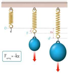
For example, imagine the simple act of hanging a weight from a tension spring. In this single-step test, force is the control dimension. The downward load generated by the weight was defined prior to its application, and that load is the cause of change in the specimen. The effect, observed as an elongation of the spring, is then measured in terms of the secondary measurement dimension, displacement.
When designing a test like this, one may naturally wonder which dimension– control or measurement– is more important to the quality of the test results. The control dimension creates the change in the specimen, which certainly seems primary to the test. But the measurement dimension, which provides previously unknown information that is now required to solve for the dependent variable, is critical as well…
As it turns out, deciding which dimension is most important is a false choice. Both dimensions are important, and this can be understood through the functional relationship of mechanics.
Understanding the Functional Relationship
The spring test above is used to solve for the most basic mechanical performance specification: specimen stiffness. To calculate stiffness, the force applied to the specimen is divided by its resulting elongation, typically expressed in units of lbf/in or N/mm. The stiffness specification is noteworthy because it concisely illustrates the universal rationale behind all mechanical tests: to gain a better understanding of the relationship between the force and displacement dimensions as they interact through some product or material of interest.
Because characterizing the relationship between dimensions is the ultimate goal– rather than just examining one dimension in isolation– any error incurred in a given dimension will necessarily discount the value of measurements taken the with other dimension. For example, when performing a stiffness characterization, our intuitions alone can predict it would be wasteful to generate the applied load with a Class 000 reference weight if we then planned to use a cheap plastic ruler to measure spring displacement. Similarly, using a sub-micron glass scale to measure elongation would be absurd if the load were being generated by a dumbbell from our local gym.
The essential takeaway: because every test result is a product of calculations based on both the control and measurement dimensions, any significant error introduced into either dimension will corrupt mechanical test results.
Static Testing versus Dynamic Testing
Hooke’s Law
Another foundational convention of mechanical testing is that all test variations fit into two basic categories: static or dynamic tests.
The basic operation of a static test is to increase the load being applied to a specimen at a rate so gradual that its effect is indistinguishable from an isometric load. This is to say, the measurement results would be no different if the test was slowed even further.
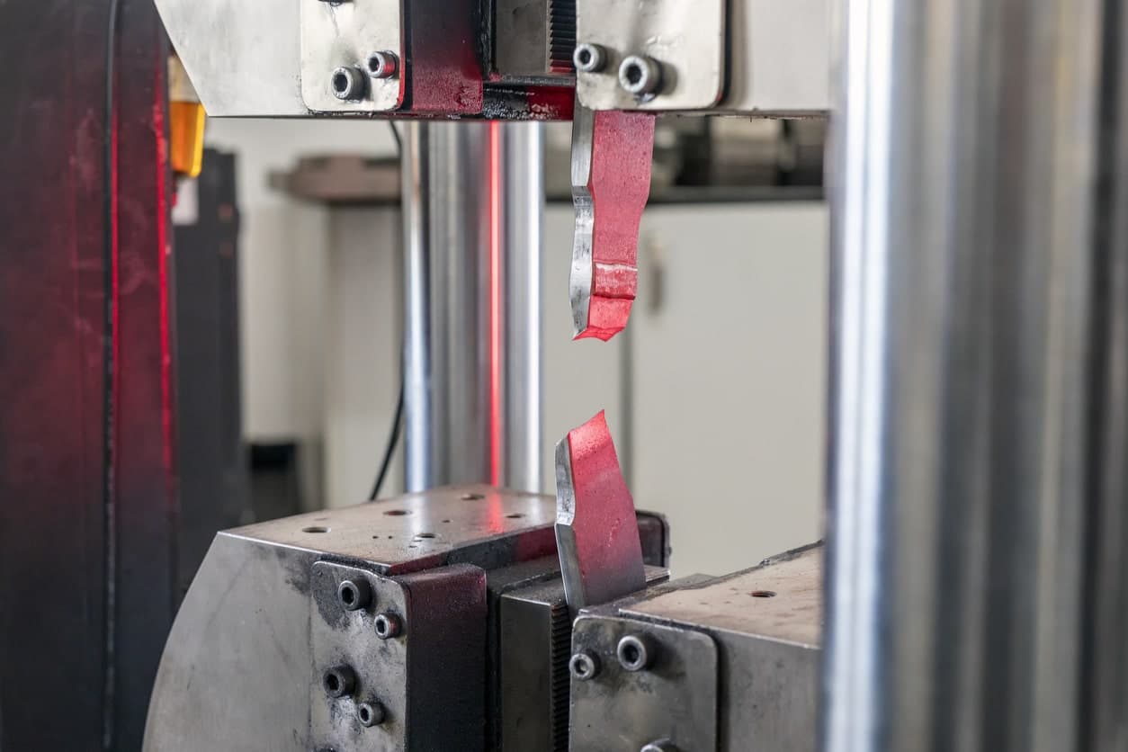
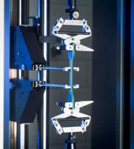
A textbook example of a static test is ASTM E8, Tension Testing of Metallic Materials. In this method, a piece of metal is prepared by being cut into a shape commonly referred to as a “dogbone”. The dogbone is then inserted into the grips of a mechanical test machine and stretched at a fixed velocity (displacement rate) until the dogbone eventually breaks. Since the displacement rate of ASTM E8 is fixed and quite slow, it typifies a common static test.
The fixed rates that control a static test can be defined in terms of either load rate or displacement rate. Load rates are expressed as the change in force or stress per unit of time. Displacement rates are expressed as the change in length, height or strain per unit of time. As is the case in ASTM E8, static tests typically control the rate of displacement while measuring a resultant force (rather than the converse).
Most static tests are designed to examine how the specimen will perform under either tensile or compressive loading, but not both. A test that stays within a single loading mode is technically referred to as a monotonic test.
Dynamic tests differ from static tests by a couple key features. Rather than just increasing the load or displacement at a fixed rate, dynamic tests can use load or displacement rates that are continuously changing over time. Dynamic tests also use cyclic actuation to subject their specimen to directional changes in the applied load and displacement, as opposed to static tests, which are typically monotonic.
The aim of dynamic testing is to characterize how a specimen’s performance will degrade over repeated cycles of loading and unloading or loading and reverse-loading. Dynamic tests typically use force as their control dimension, although test control can be based off either dimension. When force is the control dimension, tests examine how the compliance (elongation or compaction) of a specimen increases under each subsequent loading iteration, with the trend of reduced specimen stiffness over time being the most common relationship of interest.
The applied loads of a dynamic test typically follow a sinusoidal waveform that is cycled between fixed upper and lower force limits at a defined frequency (cycles per unit of time). These tests can stay within a single loading mode by loading and unloading the specimen in either the tension or compression mode. The test can also span both loading modes by loading and then reverse-loading the specimen across both tension and compression. Tests that traverse both loading modes are often referred to as bimodal or bidirectional tests. Regardless of which loading modes are at work, dynamic tests are commonly referred to as cyclic, fatigue or accelerated-life tests.
Static tests will run until some predetermined event occurs such as a load or displacement limit being reached or the specimen breaks. While static tests usually use a single condition to conclude the test, dynamic tests are inherently more complex and often must consider multiple conditions simultaneously while determining when to conclude the test. These conditions could include parameters such as test duration, cycle count, exceeding a displacement threshold, falling below a force threshold, or (naturally) a specimen break. A dynamic test will continue until one of these conditions is met indicating the specimen has been sufficiently exercised.
Force Measurement in the Test Apparatus
One of the reasons a nearly countless variety of load cells are available is that each form factor had its own strengths and weaknesses. This wide selection of load cell options has created some degree of application-specificity in the marketplace. So, it is important to understand whether your particular mechanical testing application is monotonic or bidirectional, involves well-behaved static loads or unrelenting dynamics, can be completed is less than a minute or will require millions of cycles… because all of these factors help determine which particular load cell design will be best suited for your particular application.
Making the correct choice while considering all of these variables may sound a bit daunting! Candidly, it often is. After all, very few among us are experts on the broad topic of load cell technology and application. But, the fact remains that choosing the right load cell is one of the most critical decisions in the entire test method design process—so it needs to be correct.
But there is good news: if you are unsure of which load cell design will best fit your application, you have access to the Transcell Technology Force Measurement Experts. With decades of experience in the design, manufacture and implementation of force measurement systems, Transcell is your best resource for all technical and product support. Transcell has the best sensors and instrumentation for the job and is excited to help.
Please give us a call